This is a continuation of my
self-regenerating destructible object project; the base voxel object structure referenced here is explained in more detail in my previous post.
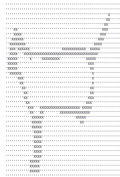
Once I got the basic system of units that could be deformed and would gradually regenerate themselves, the next step was to implement a system to import custom meshes and turn them into these voxel units, or "voxelize" them. Basically this is just taking a model and filling it up with little boxes that can be destroyed individually. In the clip below you see a cat where the left half is the original model and the right half is the voxelized version of it:
In my voxel object system, every collection of voxels that make up one object, or
VoxelUnit, is made up of a bounding box full of voxels that can be activated and deactivated as needed. Even something like a sphere is technically a full box of voxels, but the voxels that are not part of the sphere are made completely inactive and it's as if they were not a part of the shape.
Although each step is very involved, there are, conceptually, only a few steps in actually voxelizing a model:
- import the model into a usable structure
- calculate the bounding box of the model and create an empty
VoxelUnit
- activate the voxels that intersect with the model's faces
- fill in the middle of the model if desired
I only implemented functionality to import .objs with triangular faces, but allowing for other formats should mostly just affect how the model is imported. It may also affect the detection of voxels intersecting faces if the faces are quads or a mixture of quads and tris.
I set up a simple struct to hold all of the mesh data in a way that would be easily accessible:
struct Obj

{

    vector<Vector3> vertices;

     //each tri is a vector of length 3 of the actual vertex values

     //rather than a vertex index for ease of access

    vector<vector<Vector3>> tris;

     //the normal for each tri

    vector<Vector3> normals;

     //bounding box dimensions

    Vector3 boxDimensions;

     //the left, bottom, back corner of the model

    Vector3 bottomLeftBack;

}
To determine the
boxDimensions and
bottomLeftBack I keep track of the highest and lowest values in each dimension of the points as the bottom, left, back corner and top, right, front corner of the bounding box. These corner points do not necessarily correspond to a vertex, just the highest and lowest value of any vertex in the object in each dimension. Once all the vertices are loaded in, the
boxDimensions can be found by subtracting the bottom, left, back corner from the top, right, front corner. It is important to hold onto
bottomLeftBack for later to align our
VoxelUnit with the model vertices.
The face normals will also be useful later for determining intersection with faces. You may be able to read them in from your model file, but I am just calculating them to be safe; to do that you simply find the cross product of the vectors that represent two of the sides and share a starting point:
for(int i=0;i<obj->tris.size();i++)

{

    Vector3 u = obj->tris[i][1] - obj->tris[i][0];

    Vector3 v = obj->tris[i][2] - obj->tris[i][0];


    Vector3 norm = u.Cross(v);

    norm.Normalize();

    obj->normals.push_back(norm);

}
Once you have the model data in an accessible format it is time to create a
VoxelUnit the size of the
Obj boxDimensions. To do this I set up an additional constructor for
VoxelUnit that takes in an
Obj* and a voxel size so that it can construct the model using the
Obj to the level of detail as determined by the voxel size.
The first thing that needs to be done is, given the dimensions of the bounding box of the model, determine how many voxels across the object will be in each direction. This is pretty straightforward, and very similar to determining it based on just dimensions, but you have to be a bit more careful and conservative about tweaking the dimensions to come to an even voxel count in each direction. Because the object is based on a model, we want to make sure the new bounding box will fully encompass the model.
VoxelUnit::VoxelUnit(Obj* obj,float voxelSize)

{

     //just get the original necessary dimensions

    mDimensions=obj->boxDimensions;

    mVoxelSize=voxelSize;

     //determine the number of voxels across each dimension will fit in the bounding box

    mVoxelsDim=mDimensions/mVoxelSize;

     //number of voxels must be an integer

     //using the ceiling function so as not to round down and clip off parts of the model

    mVoxelsDim=Vector3(ceil(mVoxelsDim.x),ceil(mVoxelsDim.y),ceil(mVoxelsDim.z));

     //calculate new actual dimensions

    mDimensions=mVoxelsDim*mVoxelSize;

     //set the position to the center of the object for easier intersection checking

    mPosition=obj->bottomLeftBack+(obj->boxDimensions/2);

}
Next you need to populate your
Voxel array; this is the most involved and time-consuming part of the process because to determine whether or not each
Voxel is active I am checking finding each edge of each
Voxel and checking them against faces until it either finds one it intersects with, or runs out of faces to check.
For each
Voxel at index x,y,z:
//set a temporary depth and timer value

mVoxels[x][y][z].depth=EMPTY;

mVoxels[x][y][z].regenTimer=0;


//find the middle position of the voxel

Vector3 pos=mPosition-(mVoxelsDim*mVoxelSize/2);

Vector3 index(x,y,z);

pos+=index*mVoxelSize;


//find the upper and lower bounds of the individual voxel

Vector3 rightTopFront=pos+(Vector3(1,1,1)*(mVoxelSize/2));

Vector3 leftBottomBack=pos-(Vector3(1,1,1)*(mVoxelSize/2));


//holder for the edges

vector<vector<Vector3>> edges;

//holder for a single edge with two Vector3 endpoints

vector<Vector3> edge;


//find top right edge

edge.push_back(rightTopFront);

edge.push_back(Vector3(rightTopFront.x,rightTopFront.y,leftBottomBack.z));

edges.push_back(edge);

edge.clear();


//find bottom right edge

edge.push_back(Vector3(rightTopFront.x,leftBottomBack.y,rightTopFront.z));

edge.push_back(Vector3(rightTopFront.x,leftBottomBack.y,leftBottomBack.z));

edges.push_back(edge);

edge.clear();


//continue like this for each of the twelve edges
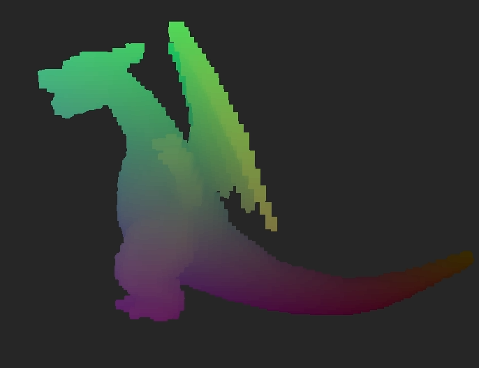 |
| Who's that Pokemon? |
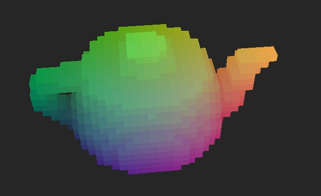
Originally, once I had found all the
Voxel's edges I checked each edge against every face in the model until one of them intersected or I ran out of faces. As you might imagine, that was very very very time consuming. To cut down on this time, I decided to generate an index range for each
Voxel edges would only be checked against faces whose bounding boxes in terms of
Voxel indices contained that
Voxel. This was incredibly effective at cutting down time. A low quality (high voxel size) import of my test teapot model went from taking upwards of half and hour to taking under a minute. This allowed me to decrease the voxel size, thus increasing the import quality, while keeping the import time reasonable.
To find these index-based bounding boxes for each face, I first found the face's true-coordinate bounding box in very much the same way I did with the entire model, and then I used the
VoxelUnit's traits to get the bounding box in terms of object-specific indices:
//create a local structure to hold the limits

struct Limits

{

    Vector3 upper;

    Vector3 lower;

};


//vector to hold the limits for all the faces

//want to hold onto them so they don't need to be recalculated

vector<Limits> indexLims;


//find limits for every face

for(int i=0;i<obj->tris.size();i++)

{

    Limits lim;

     //set limits to the upper and lower limits of the whole VoxelUnit

    lim.upper=mPosition-(mDimensions/2);

    lim.lower=mPosition+(mDimensions/2);


     //narrow down to the limits of the actual limits of just the one face

    for(int j=0;j<obj->tris[i].size();j++)

    {

        if(obj->tris[i][j].x>lim.upper.x)

            lim.upper.x=obj->tris[i][j].x;

        if(obj->tris[i][j].x<lim.lower.x)

            lim.lower.x=obj->tris[i][j].x;


        if(obj->tris[i][j].y>lim.upper.y)

            lim.upper.y=obj->tris[i][j].y;

        if(obj->tris[i][j].y<lim.lower.y)

            lim.lower.y=obj->tris[i][j].y;


        if(obj->tris[i][j].z>lim.upper.z)

            lim.upper.z=obj->tris[i][j].z;

        if(obj->tris[i][j].z<lim.lower.z)

            lim.lower.z=obj->tris[i][j].z;

    }


     //the bottom, left, back corner of the VoxelUnit

    Vector3 bottomCorner=mPosition-(mDimensions/2);


     //find index values at the limits

    lim.upper-=bottomCorner;

    lim.lower-=bottomCorner;

    lim.upper/=mVoxelSize;

    lim.lower/=mVoxelSize;


     //indices must be integers

    lim.lower=Vector3((int)lim.lower.x,(int)lim.lower.y,(int)lim.lower.z);

     //be conservative with upper limit so as to not cut off any results

    lim.upper=Vector3(ceil(lim.upper.x),ceil(lim.upper.y),ceil(lim.upper.z));

    indexLims.push_back(lim);

}
After having determined the index bounds for each face, a quick check to make sure the current
Voxel index is within the face's index bounds before more in-depth checking can be put in place to significantly cut down on the voxelization time:
//for each Voxel at index x,y,z


for(int i=0;i<edges.size();i++)

{

    bool collides=false;

     //check each face

    for(int j=0;j<obj->tris.size();j++)

    {

     //if the Voxel is outside of the face index bounds, skip this face

        if(x>indexLims[j].upper.x || x<indexLims[j].lower.x

            || y>indexLims[j].upper.y || y<indexLims[j].lower.y

            || z>indexLims[j].upper.z || z<indexLims[j].lower.z)

            continue;


         //check triangle/segment collision to see if edge intersects face

        collides=segmentTriangleCollision(obj->tris[j],

                    obj->normals[j],

                    edges[i]);

         //if it does intersect, stop checking faces

        if(collides)

            break;

    }

    if(collides)

    {

         //fill it in if it's touching the model

        mVoxels[x][y][z].depth=CENTER;

         //voxel already active, stop checking edges

        break;

    }

}
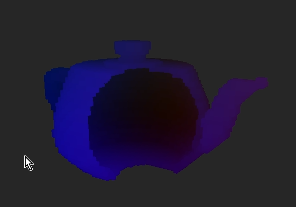 |
| Hollow teapot |
 |
| Teapot filled in |
By reassigning
Voxels that intersect with the model faces you will end up with a shell of the model. It will look like a voxelized version of the mesh until part of it is destroyed at which point you will see that it is hollow. This may be what you're going for in some cases, but I really was hoping to create solid objects. In order to do this I go through the newly generated
Voxels and reevaluate each
EMPTY one. This involves checking to see whether there is an active
Voxel in both directions along each axis going through the
Voxel being looked at. If there is an active one at some point in every direction then that currently empty
Voxel is actually in the middle of the object and should be active.
This solution is not without flaws, though. This will fill in any intentional holes in the model as well in any place which is completely encased in the rest of the object. Because of this, I have left the option of leaving the object hollow.
Hollow Object:
Solid Object:
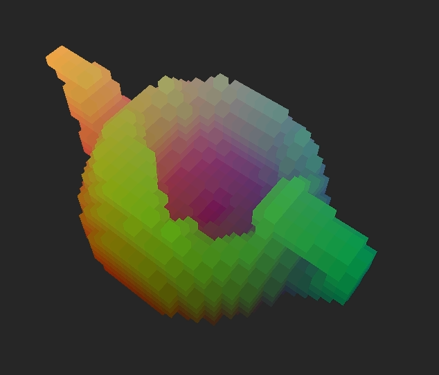
 |
| A sheet of voxelized cat. |
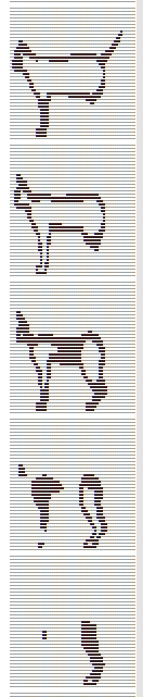
In order to avoid having to re-voxelize a mesh every time I wanted to use it, I implemented basic save an load functionality. Each voxelized object file has a header that states the dimensions of the bounding box of the object, and then a list of yz sheets for each layer of x as shown int the picture. Being able to save out these voxelizations also allows the user to edit the voxelized objects; they could fix any area that they are unhappy with how its been filled in, or manually fill in certain areas of the object. Mostly, though, this save and load functionality is convenient because loading a pre-voxelized object is magnitudes faster than voxelizing one on the go.
Check back for more updates on this project. I plan to continue it by adding more robust, non-destructive collisions, so the objects could actually be used as terrain or other mobile assets. I also plan to, at some point, get most of the calculations running through the GPU using OpenCL for increased processing speed and efficiency.

 I set up a simple system to load levels in from a very basic grid-based text file. It is set up with two grids whose layout should be the same. The first grid indicates the basic layout of anchor points and basic wall nodes and the second indicates which of the nodes should be collectibles and which type they should be.

