Thursday, April 24, 2014

The Blob Game Debacle

In physics, after successfully implementing basic sphere collision detection and resolution, we were tasked with using this collision system to simulate the behavior of both rods (objects always the same distance apart) and cables (objects never further apart than cable length). In its most basic form, I got these things working pretty well, as you can see below:

Examples of Cables and Rods respectively:


The problems started when I tried to link together four or more particles with rods to create larger object structures. The rods would become too much displaced when forces were applied to the particles and the system trying to resolve these rod collisions would make the object rapidly flail around before completely exploding itself. Obviously this is not ideal behavior, and it made our next task quite frustrating.


The assignment was to create a ball-like structure using rods and particles that could be controlled by applying force to the structure's uppermost node. I could get a triangle to do this quite well, but anything beyond that became unstable. We were also supposed to implement editable level features made from springs, rods, cables, etc which this blob-ball structure could interact with, and collectible items.

White connections are rods,
black are springs
I was able to accomplish these things with some degree of success. Due to the instability of creating a structure entirely of nodes and rods, I created one instead with a center node surrounded by border nodes. The center node is connected to the border nodes by rods so that the structures would keep its form, but the border nodes are connected to one another by springs around the outside edges so that the object has more give and applying force to the nodes does not cause such a shot to the whole object. This was relatively successful, and I was able to get some pretty fun and gloriously blobby motion working.

For the rest of the game elements I decided to go with a kind of puzzle game driven by time. The layout includes walls of nodes strung together by rods. The nodes can be assigned to be either anchor points which have an increased mass so they are less movable, or basic wall pieces that can be pushed out of the way by running into them. They can also be made collectible, with beneficial (yellow) collectibles increasing the force applied to the player for movement, thus increasing speed, and detrimental (red) ones decreasing the applied force.

I set up a simple system to load levels in from a very basic grid-based text file. It is set up with two grids whose layout should be the same. The first grid indicates the basic layout of anchor points and basic wall nodes and the second indicates which of the nodes should be collectibles and which type they should be.

In layout section of the file zeros indicate empty spaces, twos indicate anchor points, and ones indicate normal walls. In the type section Xs indicate no type, Es indicate detrimental collectibles, and Cs indicate beneficial ones.

The player can flip gravity freely throughout the level, as well as move left and right. Using this the player must navigate to the end of the puzzle while the camera slowly pans right. If the player goes off screen to the left they must restart the level. In the test setup all the walls are solid, but they have collectibles in the middles of them so the player must collect them to break the link so they can push the loose ends of the wall to the side and pass through.


Obviously one of my biggest challenges with this project was getting rod structures to function with stability, but it was also a challenge, with the code base I had, to remove nodes and things completely. The system I had was very modular and each node was entirely unaware of all the things associated with it, such as the rod colliders, the sphere collider, any gravity or spring forces, etc, so any removal had to be cleared and cleaned up across multiple systems and the object itself could not handle its own cleanup. If I were to build a system like this again, I would keep this in mind and try to make the individual nodes a bit more self aware.

Although some of the functionality and behavior isn't quite working as intended (as seen below) I am really quite happy with the system behind it (aforementioned quirks aside). I feel that I manage all the different elements well and it makes it very easy to apply different forces, collision types, and behaviors to nodes in any combination and have the system just manage itself.

Wednesday, April 23, 2014

Voxelizing Meshes

This is a continuation of my self-regenerating destructible object project; the base voxel object structure referenced here is explained in more detail in my previous post.

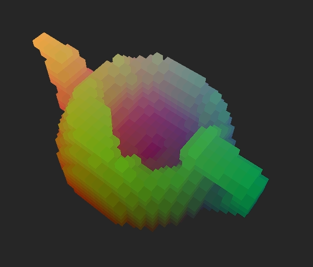
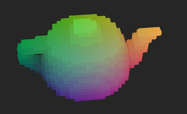
Once I got the basic system of units that could be deformed and would gradually regenerate themselves, the next step was to implement a system to import custom meshes and turn them into these voxel units, or "voxelize" them. Basically this is just taking a model and filling it up with little boxes that can be destroyed individually. In the clip below you see a cat where the left half is the original model and the right half is the voxelized version of it:


In my voxel object system, every collection of voxels that make up one object, or VoxelUnit, is made up of a bounding box full of voxels that can be activated and deactivated as needed. Even something like a sphere is technically a full box of voxels, but the voxels that are not part of the sphere are made completely inactive and it's as if they were not a part of the shape.

Although each step is very involved, there are, conceptually, only a few steps in actually voxelizing a model:
  • import the model into a usable structure
  • calculate the bounding box of the model and create an empty VoxelUnit
  • activate the voxels that intersect with the model's faces
  • fill in the middle of the model if desired
I only implemented functionality to import .objs with triangular faces, but allowing for other formats should mostly just affect how the model is imported. It may also affect the detection of voxels intersecting faces if the faces are quads or a mixture of quads and tris.

I set up a simple struct to hold all of the mesh data in a way that would be easily accessible:


struct Obj
{
    vector<Vector3> vertices;
     //each tri is a vector of length 3 of the actual vertex values
     //rather than a vertex index for ease of access
    vector<vector<Vector3>> tris;
     //the normal for each tri
    vector<Vector3> normals;
     //bounding box dimensions
    Vector3 boxDimensions;
     //the left, bottom, back corner of the model
    Vector3 bottomLeftBack;
}


To determine the boxDimensions and bottomLeftBack I keep track of the highest and lowest values in each dimension of the points as the bottom, left, back corner and top, right, front corner of the bounding box. These corner points do not necessarily correspond to a vertex, just the highest and lowest value of any vertex in the object in each dimension. Once all the vertices are loaded in, the boxDimensions can be found by subtracting the bottom, left, back corner from the top, right, front corner. It is important to hold onto bottomLeftBack for later to align our VoxelUnit with the model vertices.

The face normals will also be useful later for determining intersection with faces. You may be able to read them in from your model file, but I am just calculating them to be safe; to do that you simply find the cross product of the vectors that represent two of the sides and share a starting point:


for(int i=0;i<obj->tris.size();i++)
{
    Vector3 u = obj->tris[i][1] - obj->tris[i][0];
    Vector3 v = obj->tris[i][2] - obj->tris[i][0];

    Vector3 norm = u.Cross(v);
    norm.Normalize();
    obj->normals.push_back(norm);
}


Once you have the model data in an accessible format it is time to create a VoxelUnit the size of the Obj boxDimensions. To do this I set up an additional constructor for VoxelUnit that takes in an Obj* and a voxel size so that it can construct the model using the Obj to the level of detail as determined by the voxel size.

The first thing that needs to be done is, given the dimensions of the bounding box of the model, determine how many voxels across the object will be in each direction. This is pretty straightforward, and very similar to determining it based on just dimensions, but you have to be a bit more careful and conservative about tweaking the dimensions to come to an even voxel count in each direction. Because the object is based on a model, we want to make sure the new bounding box will fully encompass the model.


VoxelUnit::VoxelUnit(Obj* obj,float voxelSize)
{
     //just get the original necessary dimensions
    mDimensions=obj->boxDimensions;
    mVoxelSize=voxelSize;
     //determine the number of voxels across each dimension will fit in the bounding box
    mVoxelsDim=mDimensions/mVoxelSize;
     //number of voxels must be an integer
     //using the ceiling function so as not to round down and clip off parts of the model
    mVoxelsDim=Vector3(ceil(mVoxelsDim.x),ceil(mVoxelsDim.y),ceil(mVoxelsDim.z));
     //calculate new actual dimensions
    mDimensions=mVoxelsDim*mVoxelSize;
     //set the position to the center of the object for easier intersection checking
    mPosition=obj->bottomLeftBack+(obj->boxDimensions/2);
}


Next you need to populate your Voxel array; this is the most involved and time-consuming part of the process because to determine whether or not each Voxel is active I am checking finding each edge of each Voxel and checking them against faces until it either finds one it intersects with, or runs out of faces to check.

For each Voxel at index x,y,z:


//set a temporary depth and timer value
mVoxels[x][y][z].depth=EMPTY;
mVoxels[x][y][z].regenTimer=0;

//find the middle position of the voxel
Vector3 pos=mPosition-(mVoxelsDim*mVoxelSize/2);
Vector3 index(x,y,z);
pos+=index*mVoxelSize;

//find the upper and lower bounds of the individual voxel
Vector3 rightTopFront=pos+(Vector3(1,1,1)*(mVoxelSize/2));
Vector3 leftBottomBack=pos-(Vector3(1,1,1)*(mVoxelSize/2));

//holder for the edges
vector<vector<Vector3>> edges;
//holder for a single edge with two Vector3 endpoints
vector<Vector3> edge;

//find top right edge
edge.push_back(rightTopFront);
edge.push_back(Vector3(rightTopFront.x,rightTopFront.y,leftBottomBack.z));
edges.push_back(edge);
edge.clear();

//find bottom right edge
edge.push_back(Vector3(rightTopFront.x,leftBottomBack.y,rightTopFront.z));
edge.push_back(Vector3(rightTopFront.x,leftBottomBack.y,leftBottomBack.z));
edges.push_back(edge);
edge.clear();

//continue like this for each of the twelve edges
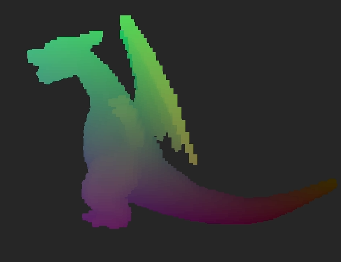

Who's that Pokemon?
Originally, once I had found all the Voxel's edges I checked each edge against every face in the model until one of them intersected or I ran out of faces. As you might imagine, that was very very very time consuming. To cut down on this time, I decided to generate an index range for each Voxel edges would only be checked against faces whose bounding boxes in terms of Voxel indices contained that Voxel. This was incredibly effective at cutting down time. A low quality (high voxel size) import of my test teapot model went from taking upwards of half and hour to taking under a minute. This allowed me to decrease the voxel size, thus increasing the import quality, while keeping the import time reasonable.


To find these index-based bounding boxes for each face, I first found the face's true-coordinate bounding box in very much the same way I did with the entire model, and then I used the VoxelUnit's traits to get the bounding box in terms of object-specific indices:


//create a local structure to hold the limits
struct Limits
{
    Vector3 upper;
    Vector3 lower;
};

//vector to hold the limits for all the faces
//want to hold onto them so they don't need to be recalculated
vector<Limits> indexLims;

//find limits for every face
for(int i=0;i<obj->tris.size();i++)
{
    Limits lim;
     //set limits to the upper and lower limits of the whole VoxelUnit
    lim.upper=mPosition-(mDimensions/2);
    lim.lower=mPosition+(mDimensions/2);

     //narrow down to the limits of the actual limits of just the one face
    for(int j=0;j<obj->tris[i].size();j++)
    {
        if(obj->tris[i][j].x>lim.upper.x)
            lim.upper.x=obj->tris[i][j].x;
        if(obj->tris[i][j].x<lim.lower.x)
            lim.lower.x=obj->tris[i][j].x;

        if(obj->tris[i][j].y>lim.upper.y)
            lim.upper.y=obj->tris[i][j].y;
        if(obj->tris[i][j].y<lim.lower.y)
            lim.lower.y=obj->tris[i][j].y;

        if(obj->tris[i][j].z>lim.upper.z)
            lim.upper.z=obj->tris[i][j].z;
        if(obj->tris[i][j].z<lim.lower.z)
            lim.lower.z=obj->tris[i][j].z;
    }

     //the bottom, left, back corner of the VoxelUnit
    Vector3 bottomCorner=mPosition-(mDimensions/2);

     //find index values at the limits
    lim.upper-=bottomCorner;
    lim.lower-=bottomCorner;
    lim.upper/=mVoxelSize;
    lim.lower/=mVoxelSize;

     //indices must be integers
    lim.lower=Vector3((int)lim.lower.x,(int)lim.lower.y,(int)lim.lower.z);
     //be conservative with upper limit so as to not cut off any results
    lim.upper=Vector3(ceil(lim.upper.x),ceil(lim.upper.y),ceil(lim.upper.z));
    indexLims.push_back(lim);
}


After having determined the index bounds for each face, a quick check to make sure the current Voxel index is within the face's index bounds before more in-depth checking can be put in place to significantly cut down on the voxelization time:


//for each Voxel at index x,y,z

for(int i=0;i<edges.size();i++)
{
    bool collides=false;
     //check each face
    for(int j=0;j<obj->tris.size();j++)
    {
     //if the Voxel is outside of the face index bounds, skip this face
        if(x>indexLims[j].upper.x || x<indexLims[j].lower.x
            || y>indexLims[j].upper.y || y<indexLims[j].lower.y
            || z>indexLims[j].upper.z || z<indexLims[j].lower.z)
            continue;

         //check triangle/segment collision to see if edge intersects face
        collides=segmentTriangleCollision(obj->tris[j],
                    obj->normals[j],
                    edges[i]);
         //if it does intersect, stop checking faces
        if(collides)
            break;
    }
    if(collides)
    {
         //fill it in if it's touching the model
        mVoxels[x][y][z].depth=CENTER;
         //voxel already active, stop checking edges
        break;
    }
}
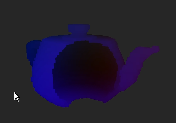

Hollow teapot
Teapot filled in
By reassigning Voxels that intersect with the model faces you will end up with a shell of the model. It will look like a voxelized version of the mesh until part of it is destroyed at which point you will see that it is hollow. This may be what you're going for in some cases, but I really was hoping to create solid objects. In order to do this I go through the newly generated Voxels and reevaluate each EMPTY one. This involves checking to see whether there is an active Voxel in both directions along each axis going through the Voxel being looked at. If there is an active one at some point in every direction then that currently empty Voxel is actually in the middle of the object and should be active.

This solution is not without flaws, though. This will fill in any intentional holes in the model as well in any place which is completely encased in the rest of the object. Because of this, I have left the option of leaving the object hollow.

Hollow Object:


Solid Object:
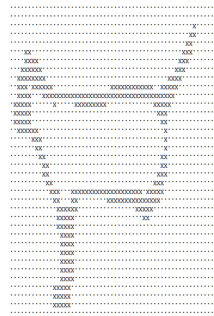


A sheet of voxelized cat.
In order to avoid having to re-voxelize a mesh every time I wanted to use it, I implemented basic save an load functionality. Each voxelized object file has a header that states the dimensions of the bounding box of the object, and then a list of yz sheets for each layer of x as shown int the picture. Being able to save out these voxelizations also allows the user to edit the voxelized objects; they could fix any area that they are unhappy with how its been filled in, or manually fill in certain areas of the object. Mostly, though, this save and load functionality is convenient because loading a pre-voxelized object is magnitudes faster than voxelizing one on the go.


Check back for more updates on this project. I plan to continue it by adding more robust, non-destructive collisions, so the objects could actually be used as terrain or other mobile assets. I also plan to, at some point, get most of the calculations running through the GPU using OpenCL for increased processing speed and efficiency.

Sunday, March 16, 2014

Physics Force Registry

This steps through how to set up the basic elements of a force registry system. This kind of system creates and manages forces and makes it easy to implement different kinds of physics behaviors such as acceleration due to gravity, planetary orbits, or spring motion simply by creating a variety of simple force-generating behaviors and applying them to basic units. To create this system I used OpenGL (freeglut) and my own Vector3 class with basic functionality. This system does not handle collision, but would not be difficult to integrate with a collision system.

The most basic element of this system is the ForceGenerator. This is a virtual base class that should be extended for each specific type of force needed. It is registered with a unit and is used to calculate the correct force and apply that force to the unit. The base class is very simple, but different members may be needed for more complex forces.

ForceGenerator.h

class ForceGenerator
{
    float Duration;
    virtual void updateForce(Unit* unit)=0;
}


updateForce(Unit* unit) is where the force is calculated and applied to unit and Duration indicates an amount of time this force should be applied. If you want a force to be applied forever setting duration to FLT_MAX and not decrementing the time if it is set to this would allow the ForceGenerator to never be removed from the registry.

One use for a ForceGenerator would be to create simple spring motion. With a simple ForceGenerator you can get fairly complex and convincing behavior with very little code:

Spring.h

class Spring:public ForceGenerator
{
    float RestLength;
    float SpringConstant;
    Unit* BaseUnit;

    Spring(Unit* base,float springConstant=1,float restLength=0);
    void updateForce(Unit* unit);
}


Spring.cpp

Spring::Spring(Unit* base,float springConstant,float restLength)
{
    BaseUnit=base;
    SpringConstant=springConstant;
    RestLength=restLenght;

    Duration=FLT_MAX; //this force will stay forever
}

void Spring::updateForce(Unit* unit)
{
    Vector3 dir = BaseUnit->Position - unit->Position;
     //get the direction of the force to be applied

    float dist = dir.Magnitude();
     //get the distance between unit and BaseUnit

    float offset = RestLength - dist;
     //get the offset from the rest length for determining the magnitude of the force

    dir.Normalize();
    Vector3 force = dir * (-SpringConstant * offset);
     //calculate the spring force

    unit->addForce(force);
}


By registering this Spring with a Unit you will get anchored spring motion with the anchor being the BaseUnit. If you would like the BaseUnit to be affected by the spring as well, you would register another Spring force with the BaseUnit and the BaseUnit of the Spring set to the Unit that the last Spring was registered with.

You can view my code for basic gravity here ( Gravity.h  Gravity.cpp )
or for planetary gravity here ( PlanetGravity.h  PlanetGravity.cpp ).

This ForceGenerator is queued for processing with a Unit pointer with a ForceRegistration which is a simple struct:

ForceRegistration.h

struct ForceRegistration
{
    Unit* unit;
    ForceGenerator* force;
}


The unit in the ForceRegistration is the one that will be passed to force->updateForce(). The Unit class at its most basic needs to contain the following:

Unit.h

class Unit
{
    Vector3 Position;
    Vector3 Forces; //Force accumulator
    Vector3 Velocity;

    float Mass;
    float InverseMass;
    float Radius;

    void update();
    void draw();
    void addForce(Vector3 force);
}


This Unit class is specifically for spherical units for simplicity, but Radius could be replaced with some kind of dimensions variable for other shapes. Also, I am storing both the mass and the inverse mass so that they do not have to be calculated each frame.

Now that we have each of the basic components involved in the force registry system we need to create the actual ForceRegistry. The ForceRegistry is entirely just a ForceRegistration holder and updater.

ForceRegistry.h

class ForceRegistry
{
    vector<forceregistration> ActiveForces;

    void add(ForceRegistration* force);
    void clear();
    void remove(int index);
    void updateForces();
}


ForceRegistry.cpp

void ForceRegistry::add(ForceRegistration* force)
{
    ActiveForces.push_back(force);
}

void ForceRegistry::clear()
{
    for(unsigned int i=0;i<ActiveForces.size();i++)
    {
        delete ActiveForces[i];
    }
    ActiveForces.clear();
}

void ForceRegistry::remove(int index)
{
    delete ActiveForces[index];
    ActiveForces.erase(ActiveForces.begin()+index);
}

void ForceRegistry::updateForces()
{
    for(unsigned int i=0;i<ActiveForces.size();i++)
    {
         //remove ForceRegistrations that have run their course
        if(ActiveForces[i]->Unit->Duration <= 0)
        {
            remove(i);
            i--;
            continue;
        }

         //update forces
        ActiveForces[i]->Force->updateForce(ActiveForces[i]->Unit);

         //decrement force duration
        if(ActiveForces[i]->Unit->Duration &lt FLT_MAX)
            ActiveForces[i]->Unit->Duration -= DeltaTime;
    }
}


The last step is to make sure that the units process and apply their accumulated forces correctly when updated. To do this you apply the velocity to the position, calculate acceleration from the accumulated forces, apply the acceleration to the velocity and then clear out the accumulated forces.

Unit.cpp

void Unit::update();
{
     //apply velocity
    Position += Velocity * DeltaTime;

     //calculate acceleration
    Vector3 acc = Forces * InverseMass;

     //apply acceleration
    Velocity += acc * DeltaTime;

     //clear force accumulator
    Forces = Vector3(0,0,0);
}


Now all that's left to do is register a ForceGenerator with a Unit.


//create the anchor and unit
Unit* anchor=new Unit();; anchor->Position=Vector3(0,0,0); anchor->Radius=1;
Unit* unit=new Unit();; unit->Position=Vector3(3,6,9); anchor->Radius=1;

//create the spring force and a force registration
Spring* spring=new Spring(anchor,1.2f,5.0f);
ForceRegistration* reg=new ForceRegistration(unit,spring);

//add the ForceRegistration to a previously made ForceRegistry
forceRegistry.add(reg);


This will result in an anchored spring object.
You can view my whole system code here.

Thursday, March 13, 2014

Self-Regenerating Destructible Objects

Destructible objects and terrain are pretty much awesome, so I figured I'd try implementing it myself (being able to program is fantastic). One thing I really wanted to focus on was making objects regenerate themselves once they had been destroyed. The main problem with destructible assets in games is that at some point everything is destroyed and one of the coolest features is eliminated; by having the assets gradually regenerate themselves this problem is avoided.

After looking into it a bit I decided that a voxel system would be the best way to accomplish this. A voxel is basically a particle with volume. By packing them together you can form a whole object or terrain whose individual voxels can be manipulated separately allowing for sections of it to be, for example, destroyed. Above is an example from my final product. The whole object is a box, but because it is made up of voxels, the upper right section can be easily removed independently.

The basic implementation was not even all that difficult. The first step for me was to set up some of the basic structures I would need. The two main ones were the Voxel which would hold information about itself and the VoxelUnit which would store and manage all the voxels contained in it. The VoxelUnit basically acts as a box that fills itself up with voxels and then makes decisions about activating and destroying each one; having this structure allows for there to be separate voxel objects that can be manipulated independently.

For this tech demo I used OpenGL and my own Vector3 class which holds three floats (x, y, z) and has basic vector math functionality.

You can view my code here.

Because the VoxelUnit handles the collision and display of each of its voxels, the Voxel itself is pretty simple.


struct Voxel
{
    Depth depth;
    float regenTimer;
};


The regenTimer is pretty obvious. To avoid instantaneous regeneration, each Voxel keeps track of how long it has been waiting to regenerate so that they can be regenerated gradually after a set amount of time.
The depth variable is a little more complex. This is used as a kind of depth identity; it is an integer defined by the following Depth enum.


enum Depth{ EMPTY=-3, DESTROYED, BORDER, SURFACE, CENTER };


EMPTY indicates a voxel that is not displayed or interacted with and will never regenerate; this allows for shapes other than a cube. In this system every VoxelUnit is made up of a box full of voxels, but by making some empty, different voxel shapes can be achieved.
DESTROYED voxels are like empty voxels, but they can be regenerated and border voxels are destroyed voxels that are adjacent to surface voxels; the VoxelUnit increments the regenTimer of these.
SURFACE and CENTER voxels are filled, but only surface voxels are rendered. Separating them also makes it convenient if you were to check surface collisions later.
EMPTY is set to -3 so that SURFACE is 0. By setting it up this way and putting the Depth values in order, you can easily check if the voxel is active by checking if its depth is greater than or equal to zero.

The VoxelUnit is basically just a Voxel manager:


class VoxelUnit
{
    ///// variables
    Vector3 Position;
    Vector3 Color;
    Vector3 Dimensions;
    Vector3 VoxelDimensions;
      //dimensions in number of voxels
    float VoxelSize;
      //the size of each side of each voxel
    Voxel*** Voxels
      //3D array to store the voxels

    ///// functions
    void update();
    void draw();

    void reassignDepth();
      //checks/resets the depth value for every Voxel
    Voxel* getAdjacent(Vector3 index);
      //returns an array of voxels adjacent to the one at index
    bool checkCollision(Vector3 c, float r);
      //check collision with a sphere at center c and radius r
};


I'll describe what each of these functions is responsible for later on, but first we need to populate our voxel array.
The first thing you need to do is determine is the voxel dimensions based on the desired dimensions of the box and the desired voxel size.

VoxelUnit.cpp

VoxelDimensions=Dimensions/VoxelSize;
VoxelDimensions=Vector3((int)VoxelDimensions.x,
                        (int)VoxelDimensions.y,
                        (int)VoxelDimensions.z);


It's important to make sure that the voxel dimensions are integers -- you don't want partial voxels.
To populate the array, you simply loop through and assign the voxels at the desired depth value.

VoxelUnit.cpp

Voxels=new Voxel**[(int)VoxelDimensions.x];
for(int x=0;x<VoxelDimensions.x;x++)
{
    Voxels[x]=new Voxel*[(int)VoxelDimensions.y];
    for(int y=0;y<VoxelDimensions.y;y++)
    {
        Voxels[x][y]=new Voxel[(int)VoxelDimensions.z];
        for(int z=0;z<VoxelDimensions.z;z++)
        {
            Voxels[x][y][z].depth=CENTER;
            Voxels[x][y][z].regenTimer=0;
            //for generating a different shape:
            //if(i>10 && i<VoxelDimensions.x-11
            //    && j>10 && j<VoxelDimensions.y-11)
            //    Voxels[x][y][z].depth=EMPTY;
        }
    }
}


Assigning all the depth values to CENTER will result in a completely filled in box; you can get creative with generating interesting shapes though by setting the depth value of certain voxels to EMPTY (they will remain empty). Including the commented section in the code above will result in a box with a tunnel through the center of it, for example.

Throughout most of these functions, most of the actual logic will happen inside the inner-most loop of the nested loop structure because it allows access to each individual voxel.

The next key element of the VoxelUnit class is the reassignDepth function. This function is used to go through and make sure every voxel has the correct depth value after there is any change to the VoxelUnit. An optimal system might disperse this function and handle reassignment more locally depending on specific situations, but for the sake of getting things working, going through and reassigning the depth after any change ensures that reassignment will always be consistent and you can avoid a lot of edge cases. The depth of each voxel is mostly determined by the depths of the voxels surrounding it; this is where our getAdjacent function is primarily utilized as well.

Instead of writing out the nested loop to access each element, assume the following code is surrounded by such a loop and x, y, and z are the index values of the voxel for each array as it was above.

VoxelUnit.cpp

////// void reassignDepth() //////
//for each Voxel in Voxels:

Vector3 index(x,y,z);
 //get an array of adjacent voxels
Voxel* adj=getAdjacent(index);


 //first we handle the voxels that are active (surface or center)
if(Voxels[x][y][z].depth>=0)
{
      //check to see if any of the adjacent voxels are inactive or "outside"
    bool outsidePresent=false;
    for(int i=0;i<6;i++)
    {
        if(adj[i].depth<0) //values less than 0 are inactive
            outsidePresent=true;
    }
    if(outsidePresent)    //if next to an inactive voxel
        Voxels[x][y][z].depth=SURFACE;
    else                  //if all surrounding voxels are active
    Voxels[x][y][z].depth=CENTER;
}


 //next we handle inactive voxels (border or destroyed)
else if(Voxels[x][y][z].depth!=EMPTY)
{
     //check to see if any of the adjacent voxels are active
    bool objectPresent=false;
    for(int i=0;i<6;i++)
    {
        if(adj[i].depth>=0) //values 0 and higher are active
            objectPresent=true;
    }
    if(objectPresent)    //if next to an active voxel
        Voxels[x][y][z].depth=BORDER;
    else                 //if all surrounding voxels are inactive
        Voxels[x][y][z].depth=DESTROYED;
}


All that getAdjacent(Vector3 index) does is return an array of the six voxels with one greater and one less index value for each dimension. To ensure that even edge voxels (index value of 0) have six adjacent voxels, I first populated the array with voxels that had a depth of EMPTY and reassigned them if the voxel actually existed.
Calling reassignDepth() after instantiating a new voxel array will sort out what is a surface, center, border, etc voxel so that you don't have to worry about that while instantiating.

The update() function is really pretty simple. It is mostly responsible for incrementing the border voxels' regenTimer and restoring the voxels that have waited the necessary time to regenerate.

VoxelUnit.cpp

////// void update() //////
//for each Voxel in Voxels:

if(mVoxels[x][y][z].depth==BORDER)
{
    Voxels[x][y][z].regenTimer+=DeltaTime; //add the time passed to the Voxel's timer
    if(Voxels[x][y][z].regenTimer>=RegenTime)
    { //if the timer has reached the required wait time, fill the voxel
        Voxels[x][y][z].depth=CENTER;
        Voxels[x][y][z].regenTimer=0;
        shouldReassign=true; //a boolean to keep track of if anything changes
    }
}

//if shouldReassign=true after each voxel is checked, call reassignDepth()


The next step is to draw the VoxelUnit. The most important thing involved with this is calculating each SURFACE voxel's position because the Voxel in my system does not hold its own position. Maybe it should, but it's easy enough to calculate, so I'm just going to stick with that.

VoxelUnit.cpp

////// void draw() //////
//for each Voxel in Voxels:

if(mVoxels[x][y][z].depth==SURFACE) //only draw surface voxels
{
     //find the position of the specific voxel
    Vector3 pos=Position-(VoxelDimensions*VoxelSize/2);
    Vector3 index(x,y,z);
    pos+=index*VoxelSize;

     //the following is for the fun rainbow coloration in my examples, based on a root Color
    Vector3 color=(Vector3(1,1,1)-Color);
    color.x*=index.x/VoxelDimensions.x;
    color.y*=index.y/VoxelsDimensions.y;
    color.z*=index.z/VoxelsDimensions.z;

    //Draw your voxel cube at pos with color
}


All of this gives you a VoxelUnit that draws and regenerates itself, now all that's left to do is make it destructible. In my tech demo I only handle destructive sphere collision, but it would not be difficult to check collisions with other shapes as well. Basically you first determine if your destructive area collides with the bounding box of the VoxelUnit at all. If it does, loop through each of the voxels and, if the voxel is active (voxel.depth>=0), check to see if it collides with the destructive area. The depth of each voxel that collides should be set to DESTROYED and, unless no voxels were destroyed, reassignDepth() should be called.

The end result should be a destructible voxel object that regenerates itself over time, like so:


Or, if the VoxelUnit is not a solid box:


As you may have noticed in that clip, I set it so that you could change the destruction radius and the regeneration speed. It's also fun to play around with VoxelSize. The VoxelUnit in the video above has 90,000 voxels (as determined by a decreased VoxelSize), but you can get some pretty cool result with much fewer as well. Obviously, though, more voxels yields much smoother results; unfortunately this leads to massive frame rate hits as well.

720 voxels:


720,000 voxels:


Another cool thing I was able to accomplish with minimal additional effort in this system was the ability to place objects in the space without the VoxelUnit regrowing through it. This seemed like a good thing to implement on the premise of increased user immersion; if the player wanted to build on or place an object within a destroyed area, the voxel object or environment should not hinder that because of its regrowing.

By placing permanent spheres and applying destructive sphere collision every frame, the VoxelUnit will regenerate around the object, but will not regrow through it.

I added the ability to remove all of the permanent spheres, and it worked beautifully:


The next step for me in this project would be to get non-destructive collision working, so that these objects could be used as terrain or interacted with in ways other than being destroyed. Another feature I would love to add to this demo would be the ability to load in and "voxelize" custom models so that any object could be turned into a self-regenerating, destructible object. I'll post an update here when I accomplish these things!

Update: I can now voxelize models!

Tuesday, February 4, 2014

Solar System

The purpose of this project was to create a force registry system for rigidbody movement that registers force generators with bodies and then applies them for a desired rotation; I then used this force registry system to create a very basic planetary motion simulation using to-scale units so that the bodies (the sun, the moon, and the eight planets) at least started at to-scale distances away from their orbital center and the correct velocity and had to-scale radii and masses and all apply gravity to one another based on these traits. Once I got the force registry system working and tested using arbitrary values which was pretty straightforward, the next biggest challenge was determining which units to use consistently across the board so that the gravitational constant (G = 6.67384e-11 m^3/kgs^2) could be scaled appropriately; I used WolframAlpha to determine these traits of the planets, sun, and moon in whatever units it returned and then compared a couple different unit options to find one that yielded semi-people-friendly numbers across the board:
These numbers were ultimately stored in doubles so as to have as few worries about loss of significant digits in multiplication as possible. The chosen units are the darkened columns: megameters for distance and yottagrams for mass; this yielded a gravitational constant of G = 6.67384e-8 Mm^3/Ygs^2. In the simulation, to speed it up so that it wasn't moving in real time and imperceptibly slowly, I set the timestep per frame to represent about 5500 seconds, which worked well for the inner planets and bumped it up to 400,000 seconds for viewing the outer planets motion; unfortunately toggling this timestep change completely throws off the inner planets.

This shows the simulation running, starting with just visibility of the inner planets in relatively stable orbits, zooming out a bit to start to see the outer planets and then switching to a preset zoom that I found was ideal for viewing the outer planets' orbits, then the time step is increased right at the end (apologies ahead of time for video quality):

You might notice that the size of the planets do not change as it is zooming out and then the inner planets become much smaller when it is switched to the "outer planet view"; this is because if the planets were left displaying to-scale, most of them would show up on-screen as maybe a pixel every once and a while; to prevent this, I implemented a toggleable function that allows you to calculate the "screen radius" of the planet and set a minimum proportion they could appear as so that they would scale if they showed up as below a certain proportion of their respective radii. For better visibility in the outer planet view, that proportion decreases for the inner planets while in this view or while viewing outer planets up-close as will be shown later. This shows this minimum size functionality:
As you can see, all of the bodies are reduced to rendering just the occasional pixel aside from the sun which stays somewhat visible in the inner-planet view mode.

Unfortunately, with the addition of this minimum scale, the earth "eats" the moon in all the system views, but I assure you: the moon is, in fact, orbiting the earth at the same time as everything else. This demonstrates the earth being targeted as the video anchor point and you can see as the earth is zoomed in on, the moon is maintaining an orbit:

The camera also has a pretty full range of motion and rotation and each planet can be selected as a more "perspective" viewpoint base that will also display the current trait information about that planet which is fun to watch as the system and orbits gradually become unstable. This first video demonstrates this targeting of each of the planetary bodies and the second one demonstrates "looking around" from the earth viewpoint.

Saturday, December 14, 2013

Predicting Physics

Predicting physics in games is the use of characteristics of an object’s current status and movement to predict where it will end up. Although there are many uses for predicting physics and trajectory in games and at least as many strategies for accomplishing it, the most basic example would be looking at two objects with constant velocities, a target and a projectile, perhaps, and determining when the projectile should be fired in order to hit the target. Given a constant velocity and a starting point for each it is easy to calculate the point at which they should collide and, from there see how long it would take for each of the objects to reach the newly calculated end point; as soon as those two time values are the same, the projectile should be fired to guarantee that it will arrive at the collision point at the same time as the target. Physics prediction can be applied to something as simple as this, or as complicated as predicting the landing location of a projectile launched into a system with multiple points of gravity acting on the projectile based on the projectile’s relative location, which is what I set out to do.

A probably the most common way complexity is added to a projectile is to have it affected by a gravity force, causing it to follow an arch trajectory rather than just a straight line until it hits something. This kind of trajectory is demonstrated in games like Angry Birds and many combat-based games that involve jumping attacks or grenade-like weapons. Based on the basic kinematic equations, which take into account the acceleration due to gravity which is constant in most systems, the calculation of the time to reach an intersection point is quadratic. Once that is accurately implemented, however, the system should work in the same way.

Obviously, the more contributing factors to a projectile’s trajectory, the more complicated prediction becomes. Sometimes it just becomes over-complicated and inefficient beyond feasibility to calculate the trajectory in one shot. Depending on the complexity and the variability of the results, an iterative process can be used to make guesses about the required initial velocity to get within a certain degree of accuracy of a target’s location. Using this strategy, an initial guess would usually be made ignoring the complicating factors, then the real final location would be calculated based on that guess and, based on where that is relative to the target location, assign it as a boundary and make another guess that is higher or lower, depending on what was wrong with the initial guess. This would be iterated through until a guess is made that falls within a certain pre-determined degree of accuracy (Millington).

In my prediction system, the landing point was one of any number of planets in a solar system and there is little correlation between the initial velocity and the landing position, as it would apply to the aforementioned iteration system. I instead used iteration to basically run a limited simulation, feeding in the initial position and velocity and stepping through each frame to determine what forces would be applied and, thus, how the trajectory would be affected frame-by-frame. I iterated through each time step until either a collision was found or the prediction timed out according to a limit I determined. You can see in the screenshots that the pink dots are positions along the trajectory of the projectile, the yellow dot with a yellow trail.

Predicting physics is not innately too processor intensive, or have any specific platform requirements. Obviously iterative prediction methods are going to be significantly more processor intensive, with an increase in demand based on how accurate the calculated trajectory must be or how long until a simulation-based iteration will continue without reaching a target. Simple things such as the first example involving constant velocities and calculating just the timing takes only a few simple operations.

Works Cited:
Millington, Ian, and John Funge. "Predicting Physics." Artificial Intelligence for Games. 2nd ed. Burlington, MA: Morgan Kaufmann, 2009. 120-33. Print.

Monday, September 30, 2013

Networking for Games Game Jam Space Jam Games and Jam

Our task: create a slightly simplified version of Space Wars that could be played by 2-4 networked players in about two and a half hours.
The result: at the end of two and a half hours we had something that almost entirely didn't run.
Over the next few days Ian the Super Fantastic and I worked to finish it up and mend all the breaks.

The end product featured:
  • independent momentum and turning
  • toggle-able gravity and center planet
  • screen-wrapped player and projectile movement
  • a color selection lobby for player differentiation

The biggest challenge we faced was, what initially seemed to be, random data loss. Turns out we were trying to pack way too much data into single packets so it would try to read in data, get about halfway through it and run out of data to read. This lead to all sorts of interesting behavior and, considering the magnitude of the problem, surprisingly few breaks. Finally we decided to send packets that contained just a data identifier and the actual data  instead of packing everything into a single packet and sending it once a frame.

One thing I think we definitely should have done differently is handling player movement over the network. Currently each player simply sends it's screen coordinates every frame and each player updates the local version of that player. What we should have done was send the player's input when it was provided and let the actual movement be handled locally, perhaps with an actual position update every couple seconds to make sure things did not go horribly, horribly awry.

There were a couple things that went well, on the other hand. I think the general gravity and momentum based movement we implemented worked very smoothly. The color-selection lobby state I made is pretty spiffy as well. Each player flies around and chooses a color as indicated by color-overlays; the game refuses to start until there is only one player per color (as determined by the host), which we felt was a better way to determine the in-game differentiation without worrying about player order and assigning things based on it.

Ian Percoco is awesome: Ian's post